Solids.. Section
The ![]() SECTION command enables you to create 2D region of the model that
is cut.
SECTION command enables you to create 2D region of the model that
is cut.
You can create a cross section through a solid as a region or as a block.
Change the UCS to World UCS
Create a BOX of dimension 4 x 4 x 6 in 2D Wireframe
as shown in Figure 1
Invoke BOX (Draw menu > Solids > Box).
Command: box
Specify corner of box or [CEnter]<0,0,0>:
Pick a point
Specify corner or [Cube/Length]: L (Length)
Specify length: 4
Specify width: 4
Specify height: 6
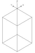 Figure 1 |
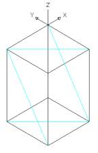 Figure 2 |
Create four light blue construction lines as shown in the
Figure 2 which will help us in creating cylinder
Create a CYLINDER of R 1.5 and creating height using the point
A and B in 2D Wireframe as shown in Figure 3.
Invoke a CYLINDER (Draw menu > Solids > Cylinder)
Command: cylinder
Current wire frame density: ISOLINES=30
Specify center point for base of cylinder or [Elliptical] <0,0,0>:
Snap to midpoint at point A
Specify radius for base of cylinder or [Diameter]: 1. 5
Specify height of cylinder or [Center of other end]: Snap
to midpoint at point B
Specify second point: Snap to midpoint at point A
Change the direction of the UCS as shown in Figure
4
Create a CYLINDER of R 1.5 and creating height using
the point C and D in 2D Wireframe as shown in Figure 4
Invoke a CYLINDER (Draw menu > Solids > Cylinder)
Command: cylinder
Current wire frame density: ISOLINES=30
Specify center point for base of cylinder or [Elliptical] <0,0,0>:
Snap to midpoint at point C
Specify radius for base of cylinder or [Diameter]: 1. 5
Specify height of cylinder or [Center of other end]: Snap
to midpoint at point D
Specify second point: Snap to midpoint at point C
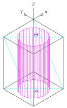 Figure 3 |
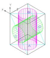 Figure 4 |
SUBTRACT the cylinders from the box and alter the
shade mode to GOURAUD SHADED from the Shade Toolbar as shown in
Figure 5
Invoke SUBTRACT (Modify > Solids Editing > Subtract)
Command: _subtract
Select solids and regions to subtract from ..
Select objects: Pick the box
Select objects: Enter
Select solids and regions to subtract ..
Select objects: Pick one cylinder
Select objects: Pick the second cylinder
Select objects: Enter
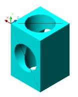
Figure 5 |
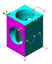 Figure 6 |
Create a SECTION at the middle of the object as
shown in Figure 6
Invoke SECTION (Draw menu > Solids > Section).
Command: _section
Select objects: Select the object
Select objects: Enter
Specify first point on Section plane by [Object/Zaxis/View/XY/YZ/ZX/3points]
<3points> Snap to endpoint at point E
Specify second point on plane:Snap to endpoint at point F
Specify third point on plane:Snap to midpoint at point G
This will create a section in the middle.
MOVE the section as shown in Figure 7
Command: _move
Select objects: Select the object
Select objects: Enter
Specify base point or displacement: Pick any point
Specify second point of displacement or <use first point as displacement>:Pick
any point to the right
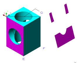
Figure 7 |
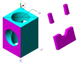 Figure 8 |
EXTRUDE the new solid model 0.5 as shown in Figure
8
Invoke an EXTRUDE (Draw menu > Solids > Extrude)
Command: extrude
EXTRUDE
Current wire frame density: ISOLINES=4
Select objects: Select the object
Select objects:Enter
Specify height of extrusion or [Path]: . 5
Specify angle of taper for extrusion <0>:Enter