Solids.. Extrude
![]() EXTRUDE
command creates 3D solids by extruding closed polylines, circles, ellipses,
closed splines, or regions.
EXTRUDE
command creates 3D solids by extruding closed polylines, circles, ellipses,
closed splines, or regions.
EXTRUDE a rectangle to create a pyramid
Click on the TOP VIEW in the view tool bar and
create a RECTANGLE of dimension 8 x 4 as shown in Figure 1
Invoke a RECTANGLE (Draw menu > Rectangle)
Command: rectangle
Specify first corner point or [Chamfer/Elevation/Fillet/Thickness/Width]:
Pick a point
Specify other corner point or [Dimensions]: @8,4
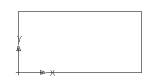
Figure 1 |
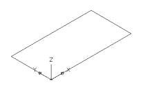 Figure 2 |
Click on the SW Isometric view in the view tool
bar as shown in Figure 2
Create a pyramid with height of 3 units the taper angle
of 10 °as shown in Figure 3
Invoke an EXTRUDE (Draw menu > Solids > Extrude)
Command: _extrude
Current wire frame density: ISOLINES=4
Select objects: Select the rectangle
Select objects: Enter
Specify height of extrusion or [Path]: 3
Specify angle of taper for extrusion <0>: 10
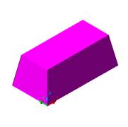
Figure 3
EXTRUDE the circle using a polyline to create a pipe
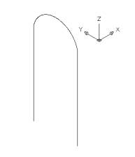
Click on the LEFT VIEW in the view tool bar and create a U shape
polyline as shown in Figure 4
Invoke a POLYLINE(Draw menu > Polyline)
Command: _pline
Specify start point: Pick a point
Current line-width is 0.0000
Specify next point or [Arc/Close/Halfwidth/Length/Undo/Width]: Draw
a straight line starting from the right
Specify next point or [Arc/Close/Halfwidth/Length/Undo/Width]: W(Width)
Specify starting width <0.0000>:0
Specify ending width <0.0000>:0
Specify next point or [Arc/Close/Halfwidth/Length/Undo/Width]: A (Arc)
Specify endpoint of arc or[Angle/CEnter/CLose/Direction/Halfwidth/Line/Radius/Second
pt/Undo/Width]: S(Second pt)
Specify second point on arc: Pick the second point of the arc in the
middle
Specify end point of arc: Pick the third point of the arc at the end
to the left
Specify next point or [Arc/Close/Halfwidth/Length/Undo/Width]: Draw
the straight line
Specify next point or [Arc/Close/Halfwidth/Length/Undo/Width]: Enter
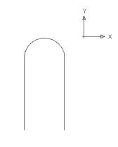 Figure 4 |
 � �Figure 5 |
Click on the UCS World
Click on the SW Isometric view in the view tool
bar as shown in Figure 5
Create CIRCLE using the polyline
as a center point as shown in Figure 6
Invoke a CIRCLE (Draw menu > Circle)
Command: _circle
Specify center point for circle or [3P/2P/Ttr (tan tan radius)]: Pick
the end point of polyline to create the circle
Specify radius of circle or [Diameter]: 1(Diameter)
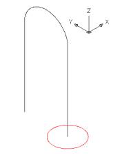
Figure 6
Select the polyline as the path of extrusion
as shown in Figure 7
Invoke an EXTRUDE (Draw
menu > Solids > Extrude)
Command: extrude
EXTRUDE
Current wire frame density: ISOLINES=4
Select objects:Select the red circle
Select objects:Enter
Specify height of extrusion or [Path]: P (Path)
Select extrusion path or [Taper angle]: Click on the polyline
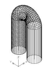 Figure 7 |
 Figure 8 |
Alter the shade mode to GOURAUD SHADED from the Shade Toolbar as
shown in Figure 8
EXTRUDE a polygone using the taper angle as +ve 30°
Click on the TOP VIEWin the view tool bar and create a POLYGON
as shown in Figure 9
Command: _polygon
Enter number of sides <6>: 6
Specify center of polygon or [Edge]:Pick the point
Enter an option [Inscribed in circle/Circumscribed about circle] <I>:
I (Inscribed in circle)
Specify radius of circle: 2
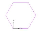
Figure 9
Click on the SW Isometric view in
the view tool bar and EXTRUDE polygon
height of 3 units and taper angle of +ve 30 °as shown in Figure 10
Invoke an EXTRUDE (Draw menu >
Solids > Extrude)
Command: _extrude
Current wire frame density: ISOLINES=30
Select objects: Select the polygon
Select objects: Enter
Specify height of extrusion or [Path]: 1
Specify angle of taper for extrusion <0>: 30(+ve angle of taper)
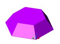
Figure 10
EXTRUDE a polygone using the taper angle as -ve 30°
Click on the TOP VIEWin the view tool bar and create a POLYGON
as shown in Figure 9
Click on the SW Isometric view in the view tool bar and
EXTRUDE polygon height of 3 units and
taper angle of -ve 30 °as shown in Figure 11
Invoke an EXTRUDE (Draw menu >
Solids > Extrude)
Command: _extrude
Current wire frame density: ISOLINES=30
Select objects: Select the polygon
Select objects: Enter
Specify height of extrusion or [Path]: 1
Specify angle of taper for extrusion <0>: -30 (-ve angle of taper)
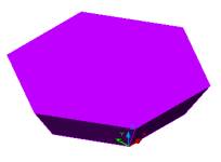
Figure 11
EXTRUDE the shape below using POLYLINE
Click on the FRONT VIEW in the view
tool bar and create the shape using polyline as shown in Figure 12, keeping
the POLAR ANGLE= 0 and ORTHO on
Invoke a POLYLINE(Draw menu > Polyline)
Command: _pline
Specify start point:Pick the point
Current line-width is 0.0000
Specify next point or [Arc/Halfwidth/Length/Undo/Width]: 4
Specify next point or [Arc/Close/Halfwidth/Length/Undo/Width]: 1
Specify next point or [Arc/Close/Halfwidth/Length/Undo/Width]: 1
Specify next point or [Arc/Close/Halfwidth/Length/Undo/Width]: 3
Specify next point or [Arc/Close/Halfwidth/Length/Undo/Width]: 2
Right click in the drawing area and invoke the shortcut and select
Arc
Specify next point or [Arc/Close/Halfwidth/Length/Undo/Width]: A (Arc)
Right click in the drawing area and invoke the shortcut and select
CENTER
Specify endpoint of arc or [Angle/CEnter/CLose/Direction/Halfwidth/Line/Radius/Second
pt/Undo/Width]: CE
Specify center point of arc: @3<180
Specify endpoint of arc or [Angle/Length]: Pick the end of the point
Right click in the drawing area and invoke the shortcut and select
Line
Specify endpoint of arc or[Angle/CEnter/CLose/Direction/Halfwidth/Line/Radius/Second
pt/Undo/Width]: L (Line)
Specify next point or [Arc/Close/Halfwidth/Length/Undo/Width]: 2
Specify next point or [Arc/Close/Halfwidth/Length/Undo/Width]: 3
Specify next point or [Arc/Close/Halfwidth/Length/Undo/Width]: 1
Specify next point or [Arc/Close/Halfwidth/Length/Undo/Width]: C (Close
the polyline)
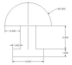
Figure 12
Click on the SW Isometric view in the view tool
bar and EXTRUDE polygon height of 4 units and taper angle of zero
as shown in Figure 13
Invoke an EXTRUDE (Draw
menu > Solids > Extrude)
Command: _extrude
Current wire frame density: ISOLINES=4
Select objects: Select the object
Select objects: Enter
Specify height of extrusion or [Path]: 4
Specify angle of taper for extrusion <0>: 0
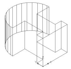 Figure 13 |
 Figure 14 |
Alter the shade mode to GOURAUD SHADED from the Shade Toolbar as shown in Figure 14