Solids.. Primitive 3D
Box, Sphere,Cylinder,Cone, Wedge & Torus
Create 3D models using 3D primitive solid objects such as boxes, spheres,
cylinder, cone, wedge and torus from Solid toolbar.
| Box | Draws a 3D box as a solid model | |
| Sphere | Draws a 3D sphere as a solid ball | |
| Cylinder | Draws a 3D cylinder as a solid tube | |
| Cone | Draws a 3D cone | |
| Wedge | Draws a 3D wedge | |
| Torus | Draws a 3D donut |
Change the UCS to ![]() World UCS
World UCS
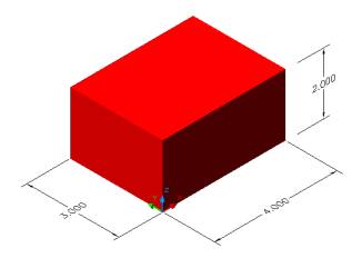
Create a BOX of dimension 4 x 3 x 2 in 2D Wireframe
as shown in Figure 1
Invoke BOX (Draw menu > Solids > Box).
Command: box
Specify corner of box or [CEnter]<0,0,0>:
Pick a point
Specify corner or [Cube/Length]: L (Length)
Specify length: 4
Specify width: 3
Specify height: 2
Alter the shade mode to GOURAUD SHADED from the Shade Toolbar as shown in Figure 2
 Figure 1 |
Figure 2 |
Create a BOX of dimension 4 x 4 x 4 in 2D Wireframe
as shown in Figure 3
Invoke BOX (Draw menu > Solids > Box)
Command: box
Specify corner of box or [CEnter]<0,0,0>:
Pick a point
Specify corner or [Cube/Length]: C (Cube)
Specify length: 4
Alter the shade mode to GOURAUD SHADED from the Shade Toolbar as shown in Figure 4
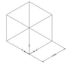
Figure 3 |
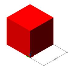
Figure 4 |
Create a SPHERE of Ø1.5 in 2D Wireframe
as shown in Figure 5.
Invoke SPHERE (Draw menu > Solids > Sphere)
Command: sphere
Current wire frame density: ISOLINES=4
Specify center of sphere <0,0,0>: > Pick
a point
Specify radius of sphere or [Diameter]:D
Specify diameter:1.5
Alter the shade mode to GOURAUD SHADED from the Shade Toolbar as shown in Figure 6.
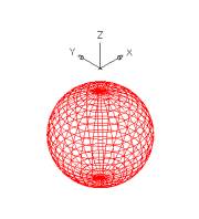 Figure 5 |
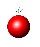 Figure 6 |
Create a CYLINDER of R 1and height 2.5 units
in 2D Wireframe as shown in Figure 7.
Invoke a CYLINDER (Draw menu > Solids > Cylinder)
Command: cylinder
Current wire frame density: ISOLINES=16
Specify center point for base of cylinder or [Elliptical] <0,0,0>:
Pick a point
Specify radius for base of cylinder or [Diameter]: 1 (Radius)
Specify height of cylinder or [Center of other end]:2.5
Alter the shade mode to GOURAUD SHADED from the Shade Toolbar as shown in Figure 8.
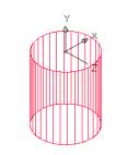 Figure 7 |
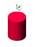 Figure 8 |
Create a CONE of R 1and height 2.5 units
in 2D Wireframe as shown in Figure 9.
Invoke a CONE (Draw menu > Solids > Cone)
Command: cone
Current wire frame density: ISOLINES=4
Specify center point for base of cone or [Elliptical] <0,0,0>: Pick
a point
Specify radius for base of cone or [Diameter]: 1
Specify height of cone or [Apex]:2.5
Alter the shade mode to GOURAUD SHADED from the Shade Toolbar as shown in Figure 10.
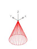 Figure 9 |

Figure 10 |
Create a WEDGE of length 3 units, wide 3 units and
height 4 units in 2D Wireframe as shown in Figure 11.
Invoke a WEDGE (Draw menu > Solids > Wedge)
Command: wedge
Specify first corner of wedge or [CEnter] <0,0,0>:Pick a point
Specify corner or [Cube/Length]: L
Specify length: 3
Specify width: 3
Specify height: 4
Alter the shade mode to GOURAUD SHADED from the Shade Toolbar as shown in Figure 12.
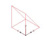 Figure 11 |
 Figure 12 |
Create a TORUS of R 2 and tube R 0.5 in 2D Wireframe
as shown in Figure 13.
Invoke a TORUS (Draw menu >
Solids > Torus)
Command:torus
Current wire frame density: ISOLINES=4
Specify center of torus <0,0,0>: Pick a point
Specify radius of torus or [Diameter]:2
Specify radius of tube or [Diameter]: 0.5
Alter the shade mode to GOURAUD SHADED from the Shade Toolbar as shown in Figure 14.
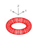
Figure 13 |
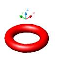
Figure 14 |
Creating a hole in the cylinder
Start drawing in the SW Isometric View
Create a CYLINDER of R2 and height 4 units as shown in Figure 15
Invoke a CYLINDER (Draw menu > Solids > Cylinder)
Command: _cylinder
Current wire frame density: ISOLINES=4
Specify center point for base of cylinder or [Elliptical]
<0,0,0>: Pick a point
Specify radius for base of cylinder or [Diameter]: 2
Specify height of cylinder or [Center of other end]: 4
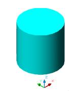 Figure 15 |
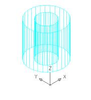 Figure 16 |
Create a SMALLER CYLINDER of R1 within the big
one using the function CENTER OF OTHER END instead of inputing
the height as shown in Figure 16.
Command: _cylinder
Current wire frame density:� ISOLINES=30
Specify center point for base of cylinder or [Elliptical] <0,0,0>:
Select OSNAP to CENTER and pick the center of the cylinder at the top
Specify radius for base of cylinder or [Diameter]: 1(Radius)
Specify height of cylinder or [Center of other end]: C (Center
of other end)
Specify center of other end of cylinder:� <Ortho on> Select OSNAP to CENTER
and pick the center of the cylinder at the bottom
SUBRACT the cylinders and
a hole will be created as shown in Figure 17
Invoke a SUBTRACT (Modify > Solids Editing > Subtract)
Command: _subtract
Select solids and regions to subtract from .
Select objects: Pick the big cylinder
Select objects: Enter
Select solids and regions to subtract
Select objects: Pick the smaller cylinder
Select objects: Enter
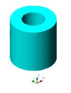
Figure 17
Create CONE on top of CYLINDER
Create a CYLINDER of
R 3 and height of 8 units in 2D Wireframe as shown
in Figure 18
Invoke a CYLINDER (Draw menu > Solids >
Cylinder)
Command: _cylinder
Current wire frame density: ISOLINES=30
Specify center point for base of cylinder or [Elliptical] <0,0,0>:
Pick a point
Specify radius for base of cylinder or [Diameter]: 3
Specify height of cylinder or [Center of other end]: 8
Alter the shade mode to GOURAUD SHADED from the Shade Toolbar as shown in Figure 19
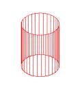
Figure 18 |
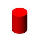 Figure 19 |
Create a CONE from the center of
the cylinder at the top in 2D Wireframe as shown
in Figure 20
Invoke a CONE (Draw menu > Solids > Cone)
Command: _cone
Current wire frame density: ISOLINES=30
Specify center point for base of cone or [Elliptical] <0,0,0>:
Select SNAP TO CENTER and pick the center of the cylinder at top
Specify radius for base of cone or [Diameter]: Select
SNAP TO QUADRANT and pick the quadrant of the cylinder
Specify height of cone or [Apex]: 5
Alter the shade mode to GOURAUD SHADED from the Shade Toolbar as shown in Figure 21
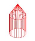 Figure 20 |
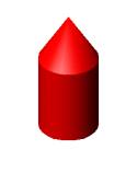 Figure 21 |
Create a CONE in the BOX
Draw a BOX (10 x 5 x
3) units in 2D Wireframe as shown in Figure 22
Invoke BOX (Draw menu > Solids >
Box)
Command: _box
Specify corner of box or [CEnter] <0,0,0>: Pick a point
Specify corner or [Cube/Length]: L
Specify length: 10
Specify width: 5
Specify height:3
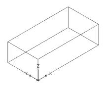 Figure 22 |
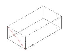 Figure 23 |
Draw a DIAGONAL CONSTRUCTION LINE on
the face as shown in Figure 23
Command: _line
Specify first point: Pick the first point on the surface of the box
Specify next point or [Undo]: Pick the second diagonal
point on the surface of the box
Draw a CONE using the midpoint
of the contruction line as shown in Figure 24
Invoke a CONE (Draw menu > Solids > Cone)
Command: _cone
Current wire frame density: ISOLINES=30
Specify center point for base of cone or [Elliptical] <0,0,0>: OSNAP
TO MIDPOINT and pick the midpoint of the construction line
Specify radius for base of cone or [Diameter]: 1
(Radius)
Specify height of cone or [Apex]: A (Apex)
Specify apex point: @5,0,0 (the length of cone in the X Direction is
5 units, and in the Y and Z Direction it is 0 unit)
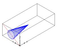
Figure 24
Alter the shade mode to GOURAUD SHADED from the Shade Toolbar as shown in Figure 25
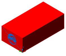
Figure 25 |
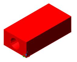 Figure 26 |
SUBTRACT the box from the
cone a hole will be created to a depth of 5 units only as shown in Figure
26
Invoke a SUBTRACT (Modify > Solids Editing > Subtract)
Command: _subtract
Select solids and regions to subtract from ..
Select objects: Pick the box
Select objects: Enter
Select solids and regions to subtract ..
Select objects: Pick the cone
Select objects: Enter