Solid Editing ... Union, Subtract and Intersect
You can use the Boolean operations to create complex solid
models out of 3D primitives solids.
The following tutorial shows you how to use Intersect, Subtract, and
Union operations.
![]() Intersect:
Intersection of two or more solids, and removes the areas outside of the
intersection. It finds the interference area of
solids objects and retains it.
Intersect:
Intersection of two or more solids, and removes the areas outside of the
intersection. It finds the interference area of
solids objects and retains it.
![]() Union:
Combines two or more solids into a single object .
Union:
Combines two or more solids into a single object .
![]() Subtract:
Select two set of solids. Select the outer object first and then the inner
object to create hole in the object. It removes
the volume of one solid from another.
Subtract:
Select two set of solids. Select the outer object first and then the inner
object to create hole in the object. It removes
the volume of one solid from another.
Create a BOX in 2D Wireframe
as shown in Figure 1
Invoke a BOX (Draw menu > Solids > Box)
Command: _box
Specify corner of box or [CEnter] <0,0,0>: Pick a point
Specify corner or [Cube/Length]: L
Specify length: 10
Specify width: 10
Specify height: 5
Create a CYLINDER in 2D Wireframe
as shown in Figure 1
Invoke a CYLINDER (Draw menu > Solids > Cylinder)
Command: _cylinder
Current wire frame density: ISOLINES=30
Specify center point for base of cylinder or [Elliptical] <0,0,0>:
Pick the midpoint at the top of the box
Specify radius for base of cylinder or [Diameter]: 2.5
Specify height of cylinder or [Center of other end]: 5
Alter the shade mode to GOURAUD SHADED from the Shade Toolbar as shown in Figure 2
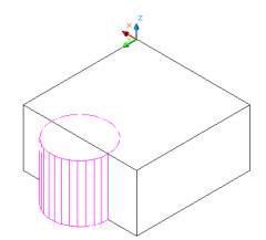 Figure1 |
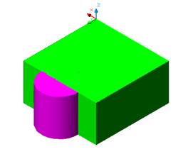 Figure 2 |
UNION by selecting both objects as shown in Figure 3
Invoke a UNION (Modify > Solids Editing > Union)
Command: _union
Select objects: Select the box
Select objects: Select the cylinder
Select objects: Enter
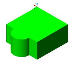 Figure 3
 |
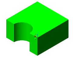
Figure 4 |
SUBTRACT the object as shown in Figure 4
Invoke SUBTRACT (Modify > Solids Editing > Subtract)
Command: _subtract
Select solids and regions to subtract from ..
Select objects: Select the box
Select solids and regions to subtract ..
Select objects: Select the cylinder
Select objects: Enter
INTERSECT the object as shown in Figure 5
Invoke INTERSECT (Modify > Solids Editing > Intersect).
Command: _intersect
Select objects: Select the box
Select objects: Select the cylinder
Select objects: Enter
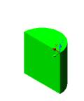
Figure 5
Creating a pattern using union, subtract and intersect command
Create two CYLINDER of Ø3 and height 1 unit.
Draw the first CYLINDER
Command: _cylinder
Current wire frame density: ISOLINES=30
Specify center point for base of cylinder or [Elliptical] <0,0,0>:
Pick any point
Specify radius for base of cylinder or [Diameter]: 3
Specify height of cylinder or [Center of other
end]: 1
Draw the second CYLINDER
Command: _cylinder
Current wire frame density: ISOLINES=30
Specify center point for base of cylinder: Click on SNAP TO QUADRANT
and draw cylinder using bottom surface of the cylinder
Specify radius for base of cylinder or [Diameter]: 3
Specify height of cylinder or [Center of other end]: 1
The two cylinder intersect in the middle as shown in Figure 6
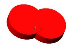
Figure 6
INTERSECT the cylinders to create an object as
shown in Figure 7
Invoke INTERSECT (Modify > Solids Editing > Intersect).
Command: _intersect
Select objects: Select the cylinder to the left
Select objects: Select the cylinder to the right
Select objects: Enter
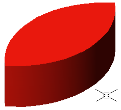
Figure 7
Draw a construction line passing through the center of the leaf, using the SNAP TO ENDPOINTS as shown in Figure 8.
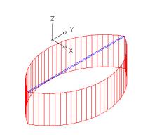
Figure 8
Create a POLAR ARRAY of the object.
Check the settings as shown in Figure 9
To select CENTER POINT pick the midpoint of the construction line.
Total number of items = 8
Angle to fill =360
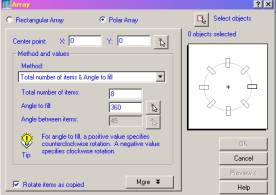
Figure 9
UNION the objects to create a pattern as shown
in Figure 10
Invoke UNION (Modify > Solids Editing > Union).
Command: _union
Select objects: Create a window to select all the object
Select objects: Enter

Figure 10
ROTATE the drawing on it bottom face and draw a construction line passing through the center of the leaf, using the SNAP TO ENDPOINTS as shown in Figure 8
EXTRUDE cylinder from the bottom of the pattern
as shown in Figure 11
Invoke an EXTRUDE (Draw menu > Solids > Extrude)
Command: _cylinder
Current wire frame density: ISOLINES=4
Specify center point for base of cylinder or [Elliptical] <0,0,0>: SNAP
TO MIDPOINT of the contruction line created to get the center of the pattern
Specify radius for base of cylinder or [Diameter]: D
Specify diameter for base of cylinder: 2
Specify height of cylinder or [Center of other end]: -3

Figure 11
SUBTRACT the object as shown in Figure 12
Invoke SUBTRACT (Modify > Solids Editing > Subtract).
Command: _subtract
Select solids and regions to subtract from ..
Select objects: Select the flower as the first set of object
Select solids and regions to subtract ..
Select objects:Select the cylinder as the second set of object
Select objects: Enter