Solid Editing .. Offset Faces
![]() Offset Faces moves all selected faces a specified distance.
Offset Faces moves all selected faces a specified distance.
Draw a BOX as shown in Figure 1
Invoke BOX (Draw menu > Solids > Box).
Command: _box
Specify corner of box or [CEnter] <0,0,0>: Pick a point
Specify corner or [Cube/Length]: L
Specify length: 10
Specify width: 2
Specify height: 10
Draw a CONSTRUCTION LINE diagonally across the
box to use it as a reference, when creating a cylinder as shown in Figure
2.
Invoke LINE (Draw>Line).
Command: _line
Specify first point:Pick the end point
Specify next point or [Undo]: Pick the diagonal end point
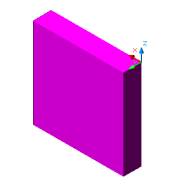 Figure 1 |
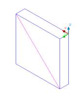 Figure 2 |
Create a CYLINDER at the middle of box as shown
in Figure 3
Invoke a cylinder (Draw menu > Solids > Cylinder)
Command: _cylinder
Current wire frame density: ISOLINES=30
Specify center point for base of cylinder or [Elliptical] <0,0,0>:
Pick the midpoint of the construction line
Specify radius for base of cylinder or [Diameter]: 2
Specify height of cylinder or [Center of other end]: 2
SUBTRACT the box from the cylinder as shown in
Figure 4
Invoke SUBTRACT (Modify > Solids Editing > Subtract).
Command: _subtract
Select solids and regions to subtract from ..
Select objects: Select the box
Select objects: Enter
Select solids and regions to subtract ..
Select objects: Select the cylinder
Select objects: Enter
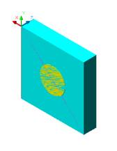 Figure 3 |
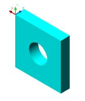 Figure 4 |
OFFSET CYLINDER by 1 unit to make the hole smaller
as shown in Figure 5
Invoke Offset Faces (Modify menu > Solids Editing
> Offset Faces).
Command: _solidedit
Solids editing automatic checking:� SOLIDCHECK=1
Enter a solids editing option [Face/Edge/Body/Undo/eXit] <eXit>:
_face
Enter a face editing option [Extrude/Move/Rotate/Offset/Taper/Delete/Copy/coLor/Undo/eXit]
<eXit>: _offset
Select faces or [Undo/Remove]: Select the front face both the box and
cylinder will be hightlighted
Select faces or [Undo/Remove/ALL]: Click on the Shift key to deselect
the box
Select faces or [Undo/Remove/ALL]:Enter
Specify the offset distance:1
OFFSET CYLINDER by -1.5�
unit to make the hole large as shown in Figure 6
Invoke Offset Faces (Modify menu > Solids Editing > Offset Faces).
Command: _solidedit
Solids editing automatic checking:� SOLIDCHECK=1
Enter a solids editing option [Face/Edge/Body/Undo/eXit] <eXit>:
_face
Enter a face editing option [Extrude/Move/Rotate/Offset/Taper/Delete/Copy/coLor/Undo/eXit]
<eXit>: _offset
Select faces or [Undo/Remove]: Select the front face both the box and
cylinder will be hightlighted
Select faces or [Undo/Remove/ALL]: Click on the Shift key to deselect
the box
Select faces or [Undo/Remove/ALL]:Enter
Specify the offset distance:-1.5
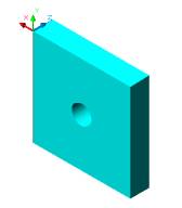 Figure 5 |
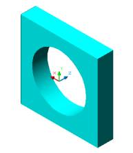 Figure 6 |
OFFSET FRONT FACE
by 3 units as shown in Figure 7
Invoke Offset Faces (Modify menu > Solids Editing > Offset Faces).
Command: _solidedit
Solids editing automatic checking:� SOLIDCHECK=1
Enter a solids editing option [Face/Edge/Body/Undo/eXit] <eXit>: _face
Enter a face editing option [Extrude/Move/Rotate/Offset/Taper/Delete/Copy/coLor/Undo/eXit]
<eXit>: _offset
Select faces or [Undo/Remove]: Select the front face and both faces will
be highlighted
Select faces or [Undo/Remove/ALL]: Enter
Specify the offset distance: 3
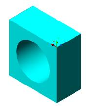
Figure 7
Create a BOX in SW Isometric view as shown in Figure 8
Invoke BOX (Draw menu > Solids > Box).
Command: _box
Specify corner of box or [CEnter] <0,0,0>: Pick a point
Specify corner or [Cube/Length]: L
Specify length: 4
Specify width:2
Specify height: 8
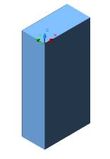
Figure 8
Invoke Offset Faces (Modify menu > Solids Editing > Offset Faces).
Command: _solidedit
Solids editing automatic checking:SOLIDCHECK=1
Enter a solids editing option [Face/Edge/Body/Undo/eXit]<eXit>: _face
Enter a face editing option[Extrude/Move/Rotate/Offset/Taper/Delete/Copy/coLor/Undo/eXit]<eXit>: _offset
Select faces or [Undo/Remove]: Select the left face
Select faces or [Undo/Remove/ALL]: Enter
Specify the offset distance: -2
POSITIVE OFFSET by 6 units will make the box face
longer as shown in Figure 10
Invoke Offset Faces (Modify menu > Solids Editing > Offset Faces).
Command: _solidedit
Solids editing automatic checking:SOLIDCHECK=1
Enter a solids editing option [Face/Edge/Body/Undo/eXit]<eXit>:
_face
Enter a face editing option[Extrude/Move/Rotate/Offset/Taper/Delete/Copy/coLor/Undo/eXit]<eXit>:
_offset
Select faces or [Undo/Remove]: Select the left face
Select faces or [Undo/Remove/ALL]: Enter
Specify the offset distance: 6
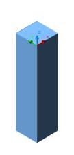 Figure 9 |
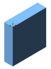 Figure 10 |
Create a Ushape with holes in them as shown in Figure 20
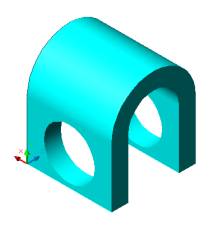
Figure 20
Draw CIRCLE and two LINES
as shown in Figure 11
Draw a CIRCLE of Ø6
Command: _circle
Specify center point for circle or [3P/2P/Ttr (tan tan radius)]: Pick
a point
Specify radius of circle or [Diameter] <0'-3 7/16">: D
Specify diameter of circle <0'-6 13/16">: 6
Draw a first LINE 7 units from the
left quadrant of the circle
Command: _line
Specify first point: SNAP TO QUADRANT and draw a line
Specify next point or [Undo]: 7
Draw a second LINE 7 units
from the right quadrant of the circle
Command: _line
Specify first point: SNAP TO QUADRANT and draw a line
Specify next point or [Undo]: 7
TRIM of the circle as shown n Figure 12
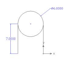 Figure 11 |
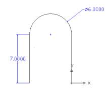 Figure 12 |
Draw an OFFSET of 2 units as shown in Figure 13
Invoke Offset (Modify menu >Offset).
Command: _offset
Specify offset distance or [Through] <0'-1">: 2
Select object to offset or <exit>: Select the line to the right
Specify point on side to offset: Pick the side to the right of the
line
Select object to offset or <exit>:Select the arc
Specify point on side to offset: Pick the outer side of the arc
Select object to offset or <exit>: Select the line to the left
Specify point on side to offset: Pick the side to the left of the line
Now connect the end points.
Alter the view to SW Isometric view from the View Toolbar as shown in Figure 14
PEDIT to combine the lines to EXTRUDE the
shape.
Command: PEDIT
Select polyline or [Multiple]: M
Select objects: Specify opposite corner: Create a window around the
object
Select objects: Enter
Convert Lines and Arcs to polylines [Yes/No]? <Y>Y
Enter an option [Close/Open/Join/Width/Fit/Spline/Decurve/Ltype gen/Undo]:
J
Join Type = Extend
Enter fuzz distance or [Jointype] <0'-0">:Enter
Enter an option [Close/Open/Join/Width/Fit/Spline/Decurve/Ltype gen/Undo]:
Enter
Make sure that the object is closed by checking with the
LIST command
If the object is open you will not be able to EXTRUDE THE OBJECT.
Invoke LIST (Tool> Inquiry> List).
Command: _list
Select objects: Select the object
Select objects: Enter
LWPOLYLINE Layer: "1"
Closed
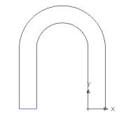 Figure 13 |
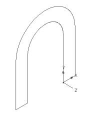 Figure 14 |
EXTRUDE the object by -10 units based on the UCS
direction as shown in Figure 15
Invoke EXTRUDE (Draw menu > Solids > Extrude).
Command: _extrude
Current wire frame density: ISOLINES=30
Select objects: Select the object
Select objects: Enter
Specify height of extrusion or [Path]: -10
Specify angle of taper for extrusion <0>: Enter
Change the UCS and be in 2D Wireframe to
draw the cylinder as shown in Figure 16
Draw a Construction line to use as a reference midpoint for drawing
a cylinder.
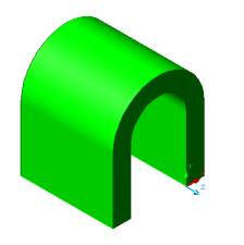 Figure 15 |
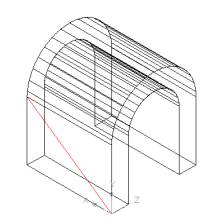 Figure 16 |
Draw a CYLINDER as shown in Figure
18
Invoke a Cylinder (Draw menu > Solids > Cylinder)
Command: _cylinder
Current wire frame density: ISOLINES=30
Specify center point for base of cylinder or [Elliptical] <0,0,0>:
Pick the midpoint of the construction line
Specify radius for base of cylinder or [Diameter]: 3
Specify height of cylinder or [Center of other end]: 0,10
(y=0 and z=10)
Specify second point: Pick the midpoint as shown in Figure as shown
in Figure 17
Alter the shade mode to GOURAUD SHADED from the Shade Toolbar as shown in Figure 19
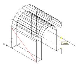 Figure 17 |
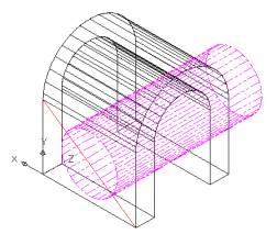 Figure 18 |
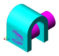
Figure 19
SUBTRACT the U shape from
the cylinder as shown in Figure 20
Invoke SUBTRACT (Modify > Solids Editing > Subtract).
Command: _subtract
Select solids and regions to subtract from ..
Select objects: Select the U shape
Select objects: Enter
Select solids and regions to subtract ..
Select objects: Select the cylinder
Select objects: Enter
Figure 20
OFFSET the CYLINDER
by 1unit to make the hole smaller as shown in Figure 21 - 23
Invoke Offset Faces (Modify menu > Solids Editing > Offset Faces).
Command: _solidedit
Solids editing automatic checking: SOLIDCHECK=1
Enter a solids editing option [Face/Edge/Body/Undo/eXit] <eXit>:
_face
Enter a face editing option[Extrude/Move/Rotate/Offset/Taper/Delete/Copy/coLor/Undo/eXit]
<eXit>: _offset
Select faces or [Undo/Remove]: Click on the border of the hole but
you will notice the box will be highlighted too as shown in Figure 21
Select faces or [Undo/Remove/ALL]: Click on the Shift key to deselect
the box as shown in Figure 22
Select faces or [Undo/Remove/ALL]:Enter
Specify the offset distance:1
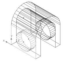 Figure21 |
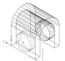 Figure 22 |

Figure23
OFFSET the CYLINDER by -ve 1.2 unitto make
the hole large as shown in Figure 24 - 26
Invoke Offset Faces (Modify menu > Solids Editing > Offset Faces).
Command: _solidedit
Solids editing automatic checking: SOLIDCHECK=1
Enter a solids editing option [Face/Edge/Body/Undo/eXit] <eXit>:
_face
Enter a face editing option
[Extrude/Move/Rotate/Offset/Taper/Delete/Copy/coLor/Undo/eXit] <eXit>:
_offset
Select faces or [Undo/Remove]: Click on the border of the hole but
you will notice the box will be highlighted too as shown in Figure 24
Select faces or [Undo/Remove/ALL]: Click on the Shift key to deselect
the box as shown in Figure 25
Select faces or [Undo/Remove/ALL]:Enter
Specify the offset distance: -1. 2
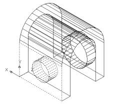 Figure 24 |
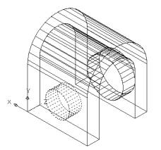 Figure 25 |
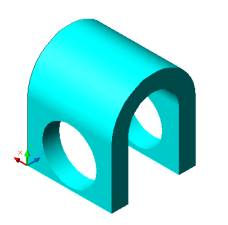
Figure 26