Solid Editing .. Move Faces
![]() Move
Faces without changing their orientation.
Move
Faces without changing their orientation.
You can edit 3D solid objects by moving faces.
Create a BOX of dimension 10 x 10 x 2 in 2D Wireframe
as shown in Figure 1
Invoke BOX (Draw menu > Solids > Box).
Command: box
Specify corner of box or [CEnter]<0,0,0>:
Pick a point
Specify corner or [Cube/Length]: L
Specify length: 10
Specify width: 10
Specify height: 2
Alter the shade mode to GOURAUD SHADED from the
Shade Toolbar as shown in Figure 2
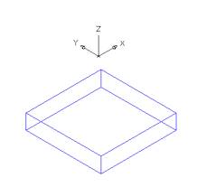 Figure 1 |
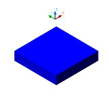 Figure 2 |
Create a CYLINDER of Ø3and
height 2 units in 2D Wireframe as shown in Figure 3
Invoke a cylinder (Draw menu > Solids > Cylinder)
Command: cylinder
Current wire frame density: ISOLINES=16
Specify center point for base of cylinder or [Elliptical] <0,0,0>:
Pick a point within a box
Specify radius for base of cylinder or [Diameter]: D
Specify diameter for base of cylinder: 3
Specify height of cylinder or [Center of other end]:2
Alter the shade mode to GOURAUD SHADED from the Shade Toolbar as shown in Figure 4
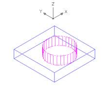 Figure 3 |
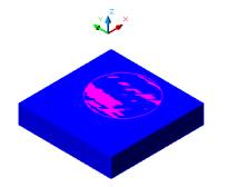 Figure 4 |
SUBRACT the
box from the cylinder and a hole will be created as shown in Figure 5
Command: _subtract
Select solids and regions to subtract from .
Select objects: Select the box
Select objects: Enter
Select solids and regions to subtract
Select objects: Select the cylinder
Select objects: Enter
Draw a temporary red diagonal construction line on the top face of the box . It will be uses as a reference for second point of displacement when we will move the cylinder as shown in Figure 6
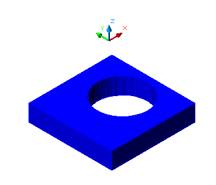 Figure 5 |
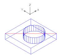 Figure6 |
MOVE the cylinder in the center
of the box.
Invoke Move Faces (Modify menu > Solids Editing >
Move Faces).
Click the top border of the hole. The top face of the
box and the inner face of the cylinder are selected at the same time as
shown in Figure 7
While pressing Shift click the top border
of the box to deselect it. Now the only selected face is the inner face
of the hole as shown in Figure 8
Press Enter.
Select the center point for the top cylinder as
the base point for displacement.
Select the center point for the top face of the box as
the second point for displacement. The hole is centered as shown in Figure
9
Command: _solidedit
Solids editing automatic checking: SOLIDCHECK=1
Enter a solids editing option [Face/Edge/Body/Undo/eXit]
Enter a face editing option [Extrude/Move/Rotate/Offset/Taper/Delete/Copy/coLor/Undo/eXit]
Select faces or [Undo/Remove]: Select the cylinder but you will notice
the box is also selected
Select faces or [Undo/Remove/ALL]: Deselect the box with pressing the
shift key
Select faces or [Undo/Remove/ALL]: Enter
Specify a base point or displacement: OSNAP Center of the cylinder
at the top
Specify a second point of displacement: OSNAP Midpoint of the diagonal
line
Enter twice to get out of the command
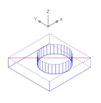
Figure 7 |
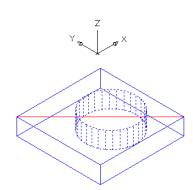 Figure 8 |
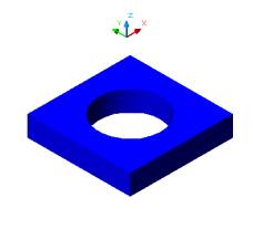
Figure 9