Solids Editing ... Delete Faces
![]() DELETE FACES option deletes selected faces. This is a quick way to
remove features such as chamfer, fillets, holes and slots.
DELETE FACES option deletes selected faces. This is a quick way to
remove features such as chamfer, fillets, holes and slots.
Create CYLINDER of D Ø13.25 and 1 unit in
height in the SW Isometric view as shown in Figure 1
Invoke a CYLINDER (Draw menu > Solids > Cylinder)
Command: _cylinder
Current wire frame density: ISOLINES=4
Specify center point for base of cylinder or [Elliptical] <0,0,0>:
Pick a point
Specify radius for base of cylinder or [Diameter]: D
Specify diameter for base of cylinder: 13.25
Specify height of cylinder or [Center of other end]: 1
Set the POLAR setting to 45° and draw the Construction line as shown in Figure 2
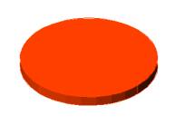 Figure 1 |
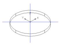 Figure 2 |
Create 4 SMALL CYLINDER of R 1.06 and height -1
unit as shown in Figure 3
Invoke a CYLINDER (Draw menu > Solids > Cylinder)
Command: _cylinder
Current wire frame density: ISOLINES=4
Specify center point for base of cylinder or [Elliptical] <0,0,0>:
Pick the top end point of the construction line
Specify radius for base of cylinder or [Diameter]: 1.06
Specify height of cylinder or [Center of other end]: -1
Alter the shade mode to GOURAUD SHADED from the Shade Toolbar as shown in Figure 4
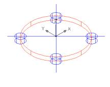 Figure 3 |
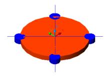 Figure 4 |
SUBTRACT the bigger cylinder from the smaller ones
as shown in Figure 5
Invoke SUBTRACT (Modify > Solids Editing > Subtract)
Command: _subtract
Select solids and regions to subtract from ..
Select objects: Pick the bigger cylinder
Select objects: Enter
Select solids and regions to subtract ..
Select objects: Pick the smaller cylinder 1
Select objects: Pick the smaller cylinder 2
Select objects: Pick the smaller cylinder 3
Select objects: Pick the smaller cylinder 4
Select objects: Enter
Change to TOP VIEW and create the center part.
Draw 4 purple Construction line as shown in Figure 6
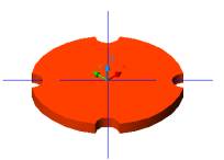 Figure 5 |
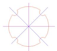 Figure 6 |
OFFSET vertical lines by 1 unit on left and right
OFFSET horizontal lines by 2 unit on top and bottom
Create the CIRCLE of R1 at both ends as shown in the Figure 7
TRIM the middle object as shown in Figure 8
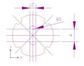 Figure 7 |
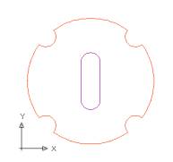 Figure 8 |
PEDIT the middle object to convert into a polyline
Command: pedit
Select polyline or [Multiple]: Select one line
Object selected is not a polyline
Do you want to turn it into one? <Y> Y
Enter an option [Close/Join/Width/Edit vertex/Fit/Spline/Decurve/Ltype
gen/Undo]: J
Select objects: Create a window around the middle object
Enter an option [Open/Join/Width/Edit vertex/Fit/Spline/Decurve/Ltype
gen/Undo]: Enter
EXTRUDE the middle object as shown in Figure 9
Invoke an EXTRUDE (Draw menu > Solids > Extrude)
Command: _extrude
Current wire frame density: ISOLINES=4
Select objects: Pick the object
Select objects: Enter
Specify height of extrusion or [Path]: 1
Specify angle of taper for extrusion <0>: Enter
Alter the shade mode to GOURAUD SHADED from the Shade Toolbar as shown in Figure 10
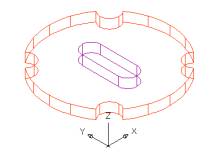 Figure 9 |
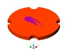 Figure10 |
SUBTRACT the outer cylinder from the middle object
as shown in Figure 11
Invoke SUBTRACT (Modify > Solids Editing > Subtract).
Command: _subtract
Select solids and regions to subtract from ..
Select objects: Select the outer cylinder
Select objects: Enter
Select solids and regions to subtract ..
Select objects: Select the object in the middle
Select objects: Enter

Figure11
DELETE the front grove as shown in Figure 14
Invoke Delete Faces (Modify menu > Solids Editing > Delete Faces).
Command: _solidedit
Solids editing automatic checking: SOLIDCHECK=1
Enter a solids editing option [Face/Edge/Body/Undo/eXit]
Enter a face editing option [Extrude/Move/Rotate/Offset/Taper/Delete/Copy/coLor/Undo/eXit]
Select faces or [Undo/Remove]:Click on the top face and the ring will
also get highlighted as shown in Figure 12
Select faces or [Undo/Remove/ALL]: Shitf+click on the border of the
top face to limit the selection to the groove face as shown in Figure
13
Select faces or [Undo/Remove/ALL]: Enter (the groove will be deleted
as shown in Figure 14
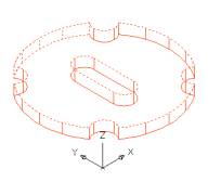 Figure 12 |
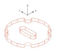 Figure 13 |
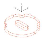 Figure 14 |
ROTATE the face as shown in Figure
18
Invoke Rotate Faces (Modify menu > Solids Editing > Rotate Faces).
Command: _solidedit
Solids editing automatic checking: SOLIDCHECK=1
Enter a solids editing option [Face/Edge/Body/Undo/eXit] <eXit>:
_face
Enter a face editing option
[Extrude/Move/Rotate/Offset/Taper/Delete/Copy/coLor/Undo/eXit] <eXit>:
_rotate
Select faces or [Undo/Remove]: Click on the top face and the ring will
also get highlighted as shown in Figure 15
Select faces or [Undo/Remove/ALL]:Shitf+click on the border of the
top face to limit the selection to the middle object as shown in Figure
16
Select faces or [Undo/Remove/ALL]: Enter
Specify an axis point or [Axis by object/View/Xaxis/Yaxis/Zaxis] <2points>:
Z
Specify the origin of the rotation <0,0,0>: Pick the center point
of the big cylinder as shown in Figure 17
Specify a rotation angle or [Reference]: 45
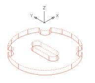 Figure15 |
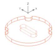 Figure16 |
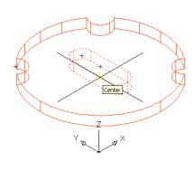 Figure17 |
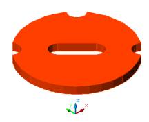
Figure18
Deleting a hole from the cylinder
Create CYLINDER of R3 and 6 units
height as shown in Figure 19
Invoke a CYLINDER (Draw menu > Solids > Cylinder)
Command: _cylinder
Current wire frame density: ISOLINES=30
Specify center point for base of cylinder or [Elliptical] <0,0,0>:
Pick a point
Specify radius for base of cylinder or [Diameter]: 3
Specify height of cylinder or [Center of other end]: 6
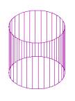
Figure 19
Create SMALL CYLINER of R
1 inside this big cylinder as shown in Figure 23
Invoke a CYLINDER (Draw menu > Solids > Cylinder)
Command: _cylinder
Current wire frame density: ISOLINES=30
Specify center point for base of cylinder or [Elliptical] <0,0,0>:
Pick the bottom as the center point as shown in Figure 20
Specify radius for base of cylinder or [Diameter]: 1
Specify height of cylinder or [Center of other end]: Pick the center
at the top as shown in Figure 21
Specify second point: Pick the center at the bottom as shown in Figure
22
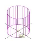 Figure 20 |
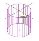 Figure 21 |
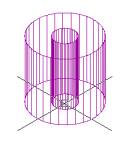 Figure 22 |
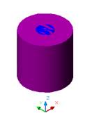
Figure 23
SUBTRACT the outer cylinder from the inner one
as shown in Figure 24
Invoke SUBTRACT (Modify > Solids Editing > Subtract).
Command: _subtract
Select solids and regions to subtract from ..
Select objects: Select the outer cylinder
Select objects: Enter
Select solids and regions to subtract ..
Select objects: Select the inner cylinder
Select objects: Enter
DELETE the inner cylinder as shown in Figure 26
Invoke Delete Faces (Modify menu > Solids Editing > Delete Faces).
Command: _solidedit
Solids editing automatic checking: SOLIDCHECK=1
Enter a solids editing option [Face/Edge/Body/Undo/eXit] <eXit>:
_face
Enter a face editing option [Extrude/Move/Rotate/Offset/Taper/Delete/Copy/coLor/Undo/eXit]
<eXit>: _delete
Select faces or [Undo/Remove]: Click on the top face of the cylinder
Select faces or [Undo/Remove/ALL]: Shitf+click on the border of the
top face to limit the selection to the inner cylinder as shown in Figure
25
Select faces or [Undo/Remove/ALL]: Enter
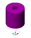 Figure 24 |
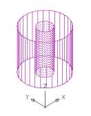 Figure 25 |
Alter the shade mode to GOURAUD SHADED from the Shade Toolbar as shown in Figure 26

Figure26
Delete a chamfer from a box
Create a BOX as shown in Figure 27Invoke a BOX (Draw menu > Solids > Box)
Command: _box
Specify corner of box or [CEnter] <0,0,0>: Pick a point
Specify corner or [Cube/Length]: L
Specify length: 10
Specify width: 2
Specify height: 10
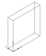
Figure27
CHAMFER an
edges by 1.5 unit as shown in Figure 30
Invoke Chamfer (Modify menu > Chamfer)
Command: _chamfer
(NOTRIM mode) Current chamfer Dist1 = 1.5000, Dist2 = 1.5000
Select first line or [Polyline/Distance/Angle/Trim/Method]: Select
face shown in Figure 28
Base surface selection...
Enter surface selection option [Next/OK (current)] <OK>: OK
Specify base surface chamfer distance <1.5000>: 1.5
Specify other surface chamfer distance <1.5000>: 1.5
Select an edge or [Loop]: Select an edge or [Loop]: Select edge as
shown in Figure 29
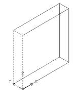
Figure 28 |
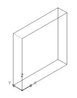 Figure 29 |
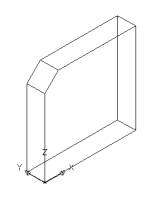 Figure 30 |
Repeat the above commands to create CHAMFER on all four sides as shown in Figure 31 - 32
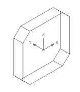 Figure 31 |
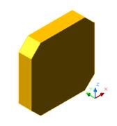 Figure 32 |
DELETE the top left chamfer as shown in Figure
34
Invoke Delete Faces (Modify menu > Solids Editing > Delete Faces).
Command: _solidedit
Solids editing automatic checking: SOLIDCHECK=1
Enter a solids editing option [Face/Edge/Body/Undo/eXit] <eXit>:
_face
Enter a face editing option [Extrude/Move/Rotate/Offset/Taper/Delete/Copy/coLor/Undo/eXit]
<eXit>: _delete
Select faces or [Undo/Remove]: Select face as shown in Figure 33
Select faces or [Undo/Remove/ALL]: Enter
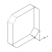 Figure 33 |
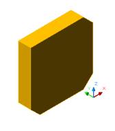 Figure 34 |
Delete a fillet from the wedge
Create WEDGE as shown in Figure 35 - 36
Invoke a WEDGE (Draw menu > Solids > Wedge)
Command: _wedge
Specify first corner of wedge or [CEnter] <0,0,0>: Pick a point
Specify corner or [Cube/Length]: L
Specify length: 10
Specify width: 2
Specify height: 10
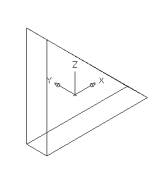 Figure 35 |
 Figure 36 |
Create FILLET as shown in Figure 39
Invoke Fillet (Modify menu > Fillet)
Command: _fillet
Current settings: Mode = NOTRIM, Radius = 0.0000
Select first object or [Polyline/Radius/Trim]: Select the edge as shown
in Figure 37
Enter fillet radius: 2
Select an edge or [Chain/Radius]: Enter as shown in Figure 38
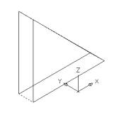 Figure 37 Figure 37 |
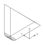 Figure 38 |
 Figure 39 |
DELETE the fillet as shown in Figure 42
Invoke Delete Faces (Modify menu > Solids Editing > Delete Faces).
Command: _solidedit
Solids editing automatic checking: SOLIDCHECK=1
Enter a solids editing option [Face/Edge/Body/Undo/eXit] <eXit>:
_face
Enter a face editing option [Extrude/Move/Rotate/Offset/Taper/Delete/Copy/coLor/Undo/eXit]
<eXit>: _delete
Select faces or [Undo/Remove]: While selecting face other faces may
also get highlighted as shown in Figure 40
Select faces or [Undo/Remove/ALL]:Shitf+click to limit the selection
as shown in Figure 41
Select faces or [Undo/Remove/ALL]: Enter
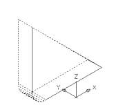 Figure 40 |
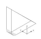 Figure 41 |
 Figure 42 |